

First Stage Lighting Design
Featuring homebrew DMX-controlled LED pixels and dimmers
The year was 2014, and I was high on my new-found discovery of the power of microcontrollers but painfully ignorant of the burgeoning field of off-the-shelf LED pixel products. So, when the opportunity came to design a new stage backdrop for my church, I jumped into a 9-month project that turned out to be the best electrical engineering education I ever received (and also a really good education in how to do things the hard way!)

The glowing, cross-hatched pipes and grid of incandescent lights to the right were the heart of this stage backdrop design. The pipes had an RGB LED at each end, each individually controlled via DMX. I also built a multi-channel TRIAC dimmer that powered each of the 15 halogen bulbs independently, also controlled by DMX.
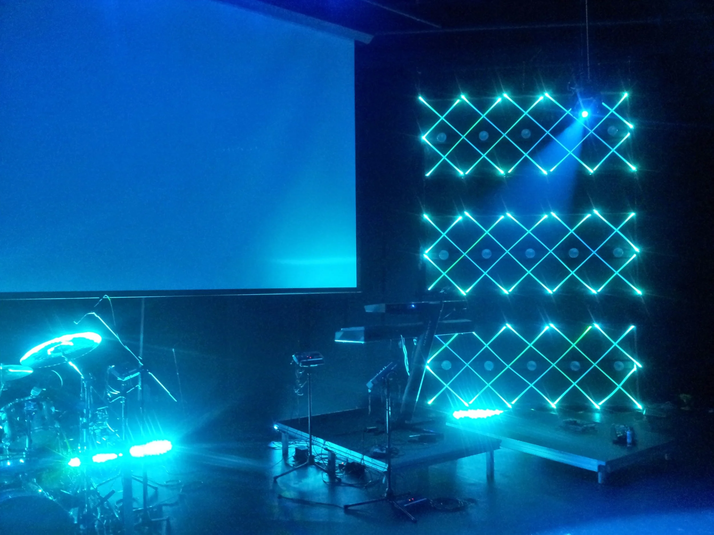
In addition to the electronics project, this was also my first full stage design after joining the team at Turning Point Church. The design goals were filling in visual space in the background to either side of the central projector screen and also adding as much back- and side-light as possible. We had a very low-channel-count DMX lighting console at this stage, so conserving fixture addresses was key as wel.

The pixel tubes were individually controllable, but due to the fixture limit on our console, I grouped the top and bottom LEDs in each of the six large rectangles in firmware so the system only appeared as 12 RGB fixtures to the console.
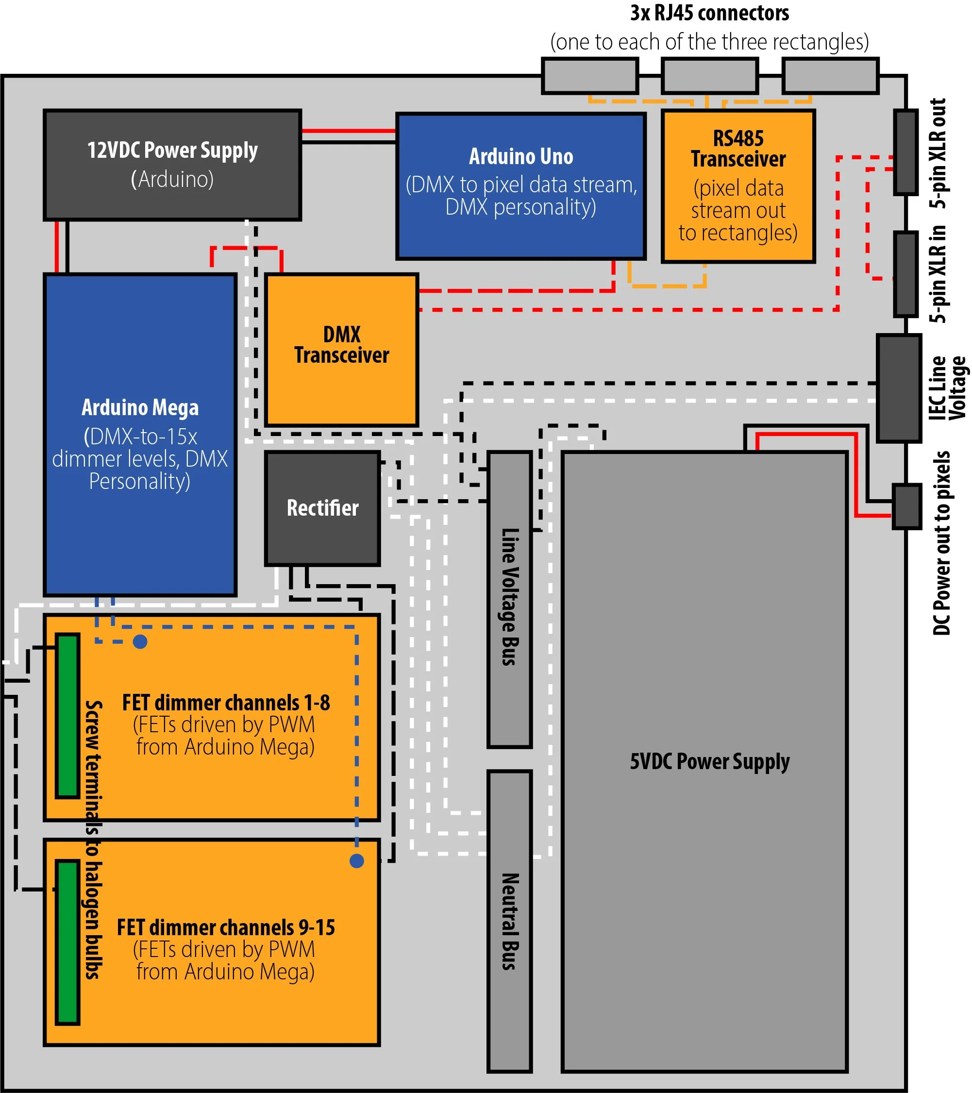
Schematic of the controller box. Each box took in AC power and DMX, then outputted my "pixel stream" proprietary RS485 data to LEDs, 5VDC to power the LEDs, and 15 channels of TRIAC-dimmed power to halogen bulbs.
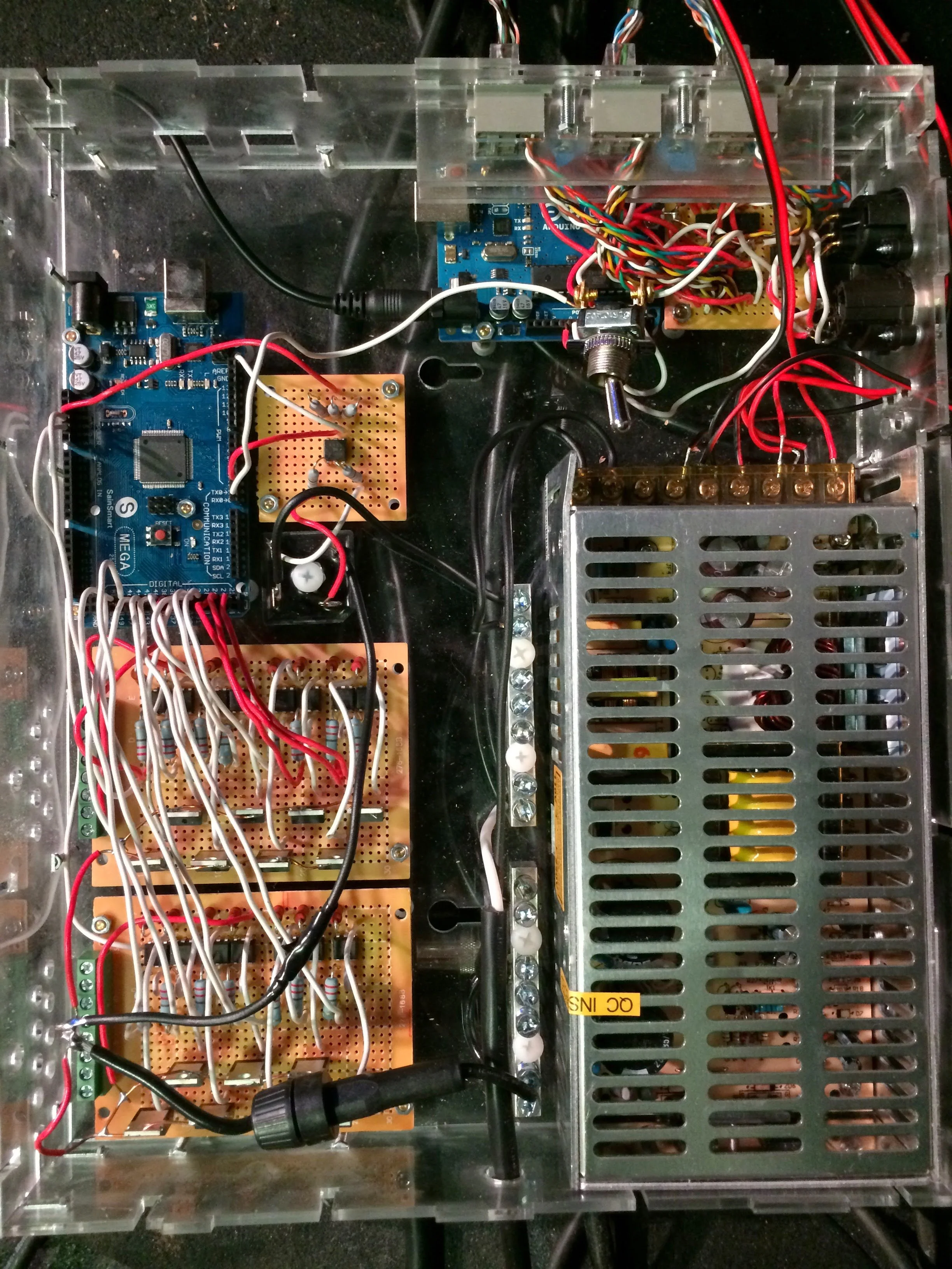
Finished controller box. I did all the soldering myself on prototype boards and cut the enclosure out on a laser cutter.
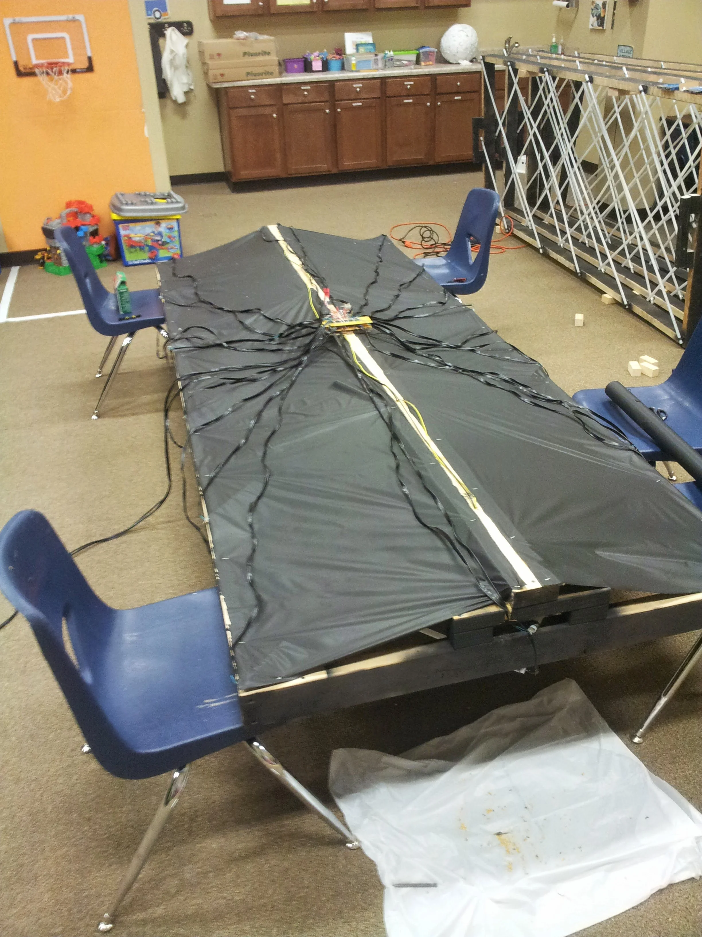
This shows the back of one of the LED rectangles. The "pixel stream" cat5 went from the controller box to a receiver on the back of the rectangle that converted the RS485 back to the right logic level for a bank of 9x 8-bit shift registers. Each of the 72 shift register outputs set the on/off state for one channel (red, green, or blue) of each of the 24 RGB LEDs on each rectangle. The Arduino in the controller calculated on/off state for each of the 216 total LED channels it served, then sent those out at around a 30hz refresh rate over the "pixel stream". The Arduino MCU was heavily taxed by this, so I had to calculate the register values with very efficient bit-wise operations in firmware. This resulted in far from the smoothest RGB dimming you've ever seen, and if I had known about the existence of off-the-shelf LED pixel products I never would've gone down this road, but it was a really great electronics education, so I don't regret it.
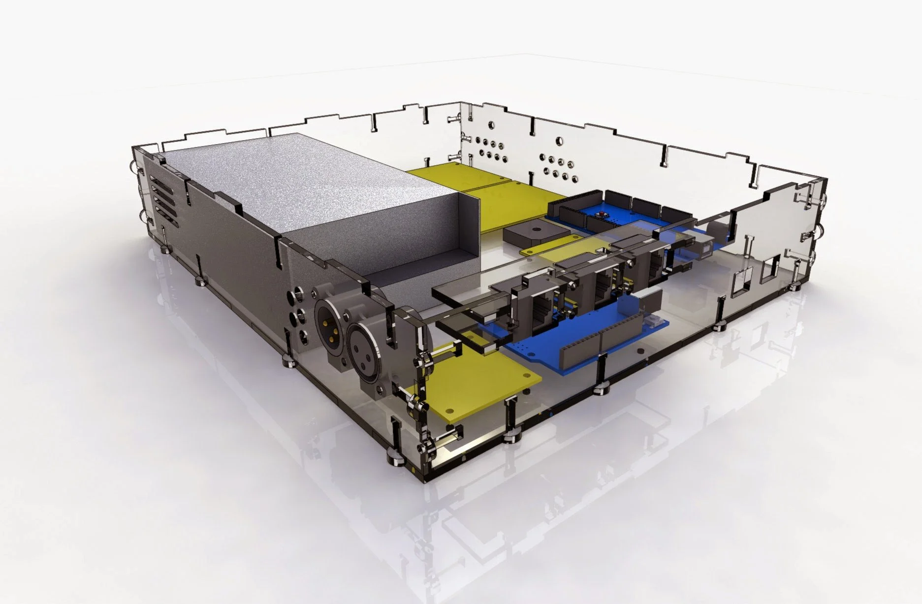
This was the final mechanical design of the controller enclosure. I had no idea I'd start doing this sort of thing for a living within the year!

Initial concept for the stage aesthetic. I did most of my sketching on a 1st gen Galaxy Note at this point in life!